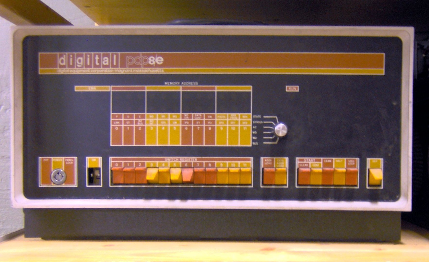
I’ve made some more progress on the DEFCON19 lanyard puzzle I’ve been working on. I think I’m finished, actually, though I still have some unanswered questions. First thing’s first: here’s a sweet picture of the PDP-8. Note the physical switches, used to manipulate the Switch Register, which gave me some trouble last time.

Recap from last time
In part one, I went through and labeled every single instruction and made notes to myself - this was necessary because I didn’t know the first thing about the PDP-8 in particular or assembly language in general.
Since I’ve worked on it more (and actually presented at AHA, which was immensely helpful in getting my thoughts all organized and such), I’ve got a bit of a higher-level understanding of what’s going on. Here are the same instructions again, but this time separated into 3 sections: the initial setup, the loop, and shutdown:
Initial setup:
0000/7301 cla, cll, iac: clear ACC and L, ACC++
0001/3224 dca: ACC->0024, clear ACC
0002/3223 dca: ACC->0023, clear ACC
0003/7404 osr: SR->ACC
0004/7550 sma, sza, reverse: skip unless ACC is positive
0005/5220 jmp 0020
0006/7041 cma, iac: complement then increment ACC (switches sign)
0007/3225 dca: ACC->0025, clear ACC

The loop:
0010/1223 tad: ACC += c(0023)
0011/1224 tad: ACC += c(0024)
0012/3223 dca: ACC->0023, clear ACC
0013/7005 ral, iac: ACC++, rotate ACC and L left
0014/1224 tad: ACC += c(0024)
0015/7224 cla, cml, ral: clear ACC, complement L, rotate ACC and L left
0016/2225 isz: 0025++ and skip next instruction if c(0025)=0
0017/5210 jmp 0010

Shutdown steps:
0020/7200 cla: clear ACC
0021/1223 tad: ACC += c(0023)
0022/7402 hlt: stop executing

storage addresses:
0023/0000 <- this is our output
0024/0000
0025/0000
A better understanding of the loop
By the end of my last blog post I understood everything except the loop. I thought that perhaps I needed to bypass the second jmp instruction at 0017, but as it turns out, that’s what is iterating through the loop.
At address 0006, the ACC (containing the value of the SR) is complemented then incremented, a process which switches the sign (so the user’s positive integer becomes a negative integer), and in the following instruction the result is saved to address 0025. In address 0016, the value of 0025 is incremented by one. If the result is not zero, nothing happens, and the following instruction on line 0017 is a jmp back to address 0010 - the beginning of the loop. However, if the result is zero, that means it’s gone through the loop the number of times specified by the SR, and the jmp instruction is skipped - which just puts the program in the shutdown section, where it copies the value at 0023 to the ACC as output, and halts execution.
Now that we understand the basic flow of the program, what the hell is going on inside the loop itself?
Those damn ral instructions
The documentation I have for ral instructions says they “rotate ACC and L left”.
In general, you might think of the rotation instructions as multiplication by two. (This is done in binary, and “rotating” the digits to the left is adding a zero on the right. Just like in base-10, this multiplies the number by 10, in base-2 it multiplies the number by 2.)
However, in this case, there are two other things going on at the same time.
- the rotation takes the Link register (L) into account as well, so the most significant (rightmost) bit of ACC becomes L.
- the rotation is circular, which means that L also becomes the least significant bit of ACC.
The Link register is generally conceived as being to the “left” of ACC, and it’s typically used for overflow. You might think of ACC+L as a single 13-bit register.
| L |   | ACCUMULATOR  |
  0       111000000000
The ral instruction will take the above starting value and turn it into this:
| L |   | ACCUMULATOR  |
  1       110000000000
Now all the digits have been shifted to the left, with the value of L register becoming the right-most digit (least-significant bit, or LSB) of the ACC, and the MSB of the ACC becoming the value of L.
How does the loop work?
Now that we understand ral, we can dissect the loop. For that, I use a C-like pseudocode. (The original assembler instructions are in C++-like double-slash comments: //.)
int SR;
int x;
int y;
int z;
int acc;
bool link;

// 0000/7301 cla, cll, iac: clear ACC and L, ACC++

acc = link = 0;
acc++;

// 0001/3224 dca: ACC->0024, clear ACC

y = acc;
acc = 0;

// 0002/3223 dca: ACC->0023, clear ACC

x = acc;
acc = 0;

0003/7404 osr: SR->ACC

acc = SR;

// 0004/7550 sma, sza, reverse: skip unless ACC is positive
// 0005/5220 jmp 0020

if (acc <= 0) goto SHUTDOWN;

// 0006/7041 cma, iac: complement then increment ACC (switches sign)

acc = -acc;

// 0007/3225 dca: ACC->0025, clear ACC

z = acc;
acc = 0;

LOOP_START:

// 0010/1223 tad: ACC += c(0023)
// 0011/1224 tad: ACC += c(0024)
// 0012/3223 dca: ACC->0023, clear ACC

acc = acc + x + y;
x = acc;
acc = 0;

// 0013/7005 ral, iac: ACC++, rotate ACC and L left

// iac:
acc = 1;
// ral:
acc = acc*2;
if (link==1) {
  acc++;
  link=0;
 }

// 0014/1224 tad: ACC += c(0024)

if (acc+y < acc)// if acc + y overflows
  link++;
acc = acc + y;

// 0015/7224 cla, cml, ral: clear ACC, complement L, rotate ACC and L left

// cla:
acc = 0;

// cml:
link++;

// ral:
if (acc >= 2048) {      // checking ACC's most significant bit
  acc = acc*2;          // shift ACC's digits left one place
  if (link == 1) acc++; // transferring L to ACC's LSB
  link = 1;             // transfering ACC's MSB to L
// now do the same as above for cases where MSB is zero:
 } else {
  acc = acc*2;
  if (link == 1) acc++;
  link = 0;
 }

// 0016/2225 isz: 0025++ and skip next instruction if c(0025)=0
// 0017/5210 jmp 0010

z++;
if (z<0) goto LOOP_START;

SHUTDOWN:

// 0020/7200 cla: clear ACC

acc = 0;

// 0021/1223 tad: ACC += c(0023)

acc = x;

// 0022/7402 hlt: stop executing

exit();

// These are just storage addresses:
// 0023/0000 <- this is our output
// 0024/0000
// 0025/0000
So.
That’s… still really confusing.
After I waded through all that for a while, I realized that there was a whole lot of unnecessary misdirection going on. For example, at the very beginning of the program, address 0024 is set to 0001 and then it’s never changed. In my pseudocode, I use the “y” variable to represent 0024, but since it never changes, I can just think of it as a 1.
The ral instructions too aren’t nearly as complicated as they could be. In the case of the first ral at 0013, ACC has just been cleared, then incremented. Furthermore, L cannot be anything but zero at that point - it looks complex, but you can change all my silly pseudocode for that instruction to just be acc = 2.
The second one at 0015 is similarly reducible. L will never be anything but 0 at that point, but then it gets complemented, so it becomes 1. ACC just got cleared, so it’s always going to start out as 0000; when the ral is executed, the 1 from L gets moved to acc’s LSB, so ACC is 0001 and L is 0.
Then the loop ends.
Conclusion
What does this mean? It means that the whole program can be reduced to pseudocode like this (remember that x is 0023, y is 0024, z is 0025, SR is user input from the Switch Register, and acc is the Accumulator):
x = 0;
y = 1;
acc = 0;

for (z=1;z<SR;z++) {
    x = x + y + acc;
    acc = 1;
}
That is, the loop always adds 2 to x (except the first time, where it just adds 1 to x, because acc is zero). This program multiplies input by two and subtracts one; algebraically: f(x) = 2x - 1, where 0 < x < 2047.
So why is this code so weird?
Why is it using those rotation instructions, and why use 0024 to mean 0001 for the whole program?
I have no idea, really. I heard that some parts of this year’s badge puzzle would play a part in next year’s as well. Maybe the output is going to be used for something badge-related.
I also thought that the setting of 0024 to 1 is particularly convenient if you plan to let the user change that later… not quite as convenient as the SR for user input, but more convenient than just hard coding an integer. Kind of like using preprocessor variables in C. Perhaps this program will be modified in the future, and the value of 0024 will change?
Links
I see that clockfort also worked on this (much later edit: site appears to have gone down, but the Internet Archive has a snapshot). Apparently he heard the same thing I did, that only the last 7 numbers were PDP-8 related.
Also, I found a post on the badge contest from Luna Lindsey. Interestingly, she says,
We found out from chatting with someone the next day that the binary was a program: PDP-8, which is simply used to square numbers. We took this as a clue that something needed to be squared. But this was also a red herring. In fact, the numbers were simply a data set used to hide another message, but not important in and of themselves.
I wonder if she was being intentionally misdirected or of something else was going on?
At any rate, it was a fun puzzle to solve. Thanks to LosT and DEFCON for the puzzle, and to AHA, Nate, and my dad for cheering me on and helping me when I got stuck. You guys rock :).
Edit: On the last iteration of this blog, I got a comment on this post by _bc_, who says, “Probably old news to you, but I found a number of similarities with the PDP-8 code located here”.
I had not seen that link before, but the layout of 1o57’s code does indeed bear a striking resemblance to the homework at that link.